Edit Database Unit (Store Operations)
Overview
A Database Unit in a flow diagram interacts with a database as part of the workflow. It allows the process to perform structured operations such as reading, writing, updating, or deleting data.
What it does:
- Connects to a database system (SQL or NoSQL).
- Executes queries or commands to manipulate data.
- Returns results for use in subsequent steps.
How it works:
- Configuration:
- Database type (e.g., MySQL, PostgreSQL, Oracle, MongoDB).
- Connection details (host, port, username, password).
- Optional: Connection pooling, timeout settings.
- Action Selection:
- Read: Fetch data using SELECT or equivalent.
- Write: Insert or update records.
- Delete: Remove records.
- Execute Procedure: Call stored procedures or functions.
- Execution:
- Sends the query to the database.
- Receives the result set or status.
- Passes data to the next unit (e.g., Mapping Unit, Decision Unit).
- Error Handling:
- Handles connection failures, query errors, or timeouts.
- Can branch to error-handling logic.
Use case:
- Document Workflow: Fetch metadata from a database before processing a document.
- Integration: Store API response data in a database.
- Reporting: Retrieve records for generating reports.
Accessing Database Unit Properties
- To view/modify the unit property, click on the Database unit. Upon clicking the unit, a property panel opens below, and the unit gets highlighted.
- The property panel will open and display the following sections:
- Input
- Processing
- Output
- By default, all sections are displayed unless you have specified panel settings in the user settings.
Input Section
- The Input section provides the details on the inbound message, and the following tabs are provided in the section:
- Data section: The Data section provides the name of the processed units of the flow.
- Message: The Message section displays the inbound message of the selected unit.
Data Section
- The section provides details on inbound messages and lists units that have already been processed. The following message details will be shown:
- Complete Message:
- The Complete Message represents the entire message payload, including:
- Message Header
- Start Message
- Input Message
- Any additional structural elements
- Message Header:
- The Message Header contains metadata about the message rather than the message's business data.
- It helps the system understand how to handle the message.
- It helps in tracking and tracing, routing, logging, and error handling.
- Start Message:
- The Start Message is the initial structure received by the Start Unit when the flow begins.
- It defines the expected input format.
- It acts as the primary data structure for processing.
- It is usually defined using XML or JSON schema.
- This message becomes the main working data object throughout the flow.
- Input Message:
- The Input Message refers to the actual incoming payload provided to the flow at runtime.
- In testing → comes from the Test Message (XML).
- In production → comes from API, queue, subscription, etc.
- It populates the Start Message structure and is then used by downstream units like Mapping, Condition, or API calls.
- Already Processed Units:
- The units that are processed before the Database unit will be listed here. The unit will be displayed by its name.
- You can click any unit to view the data processed by that unit. The message will be displayed in the
- A Search option is also provided to search for the unit name from the list.
- Enter the unit name in the search field, and the result will be displayed instantly.
- To close the search, click on the Clear (x) icon.
- A Sort icon is provided to arrange the list as needed.
- You can also arrange the units either in ascending order (A to Z) or descending order (Z to A) using the icon next to the search icon. By default, the units are arranged in ascending order.
- Click the Sort icon to switch to descending order.
- Click again to return to the default ascending order.
- A Collapse icon is provided next to the Sort icon. You can use this function to increase the message's working area for better readability and more space.
- Click on the icon to collapse the listing.
- After clicking the Collapse icon, the listing collapses.
- However, you will still be able to view the icon of the respective units.
- When you hover over the icon, you can view the names of the units. Additionally, you can click any link to view its message.
Message Section
- You can view the message of any of the units listed in the Data section.
- To view the message of any unit, click on the unit in the Data section. The message will be displayed instantly.
Find
- A Find option is also provided to find any node in the message.
- Enter the node name in the search field, and the result will be displayed instantly and highlighted.
- If more than one result is displayed, a navigation icon and a results counter are provided. You can navigate through the search results using the navigation icons.
- To close the search, click the 'x' icon.
Legends
- A legend icon is provided to help you understand the message. The color of the nodes indicates their status.
- Click the Legend icon to view the details. When you click the icon, the list will show the legend used in the message.
Adjust Message Font Size
- A Font Size box is provided to increase or decrease the message's font size.
- The current font size will be shown in the box.
- Click on the box to increase or decrease the font size.
- After clicking the Font Size box, a slider will appear below it.
- Use the slider to increase or decrease the font size.
- As you slide, the change in size will be reflected in the message instantly.
- The supported font size ranges from 8 to 72.
Switch Between Code and Tree View
- By default, the message will be displayed in Tree View.
- Click on the Switch to Code View icon.
- The inbound message gets switched to code view.
- Click the icon again to switch back to tree view mode.
Toolbar (Code View)
- A toolbar is provided to help you to edit the message efficiently. The code view provides the following icons in the toolbar:
- Find:
- Function: Searches for specific text or patterns within the document or code.
- Use Case: Quickly locating words, phrases, or code snippets.
- Replace:
- Function: Finds specific text and replaces it with new text.
- Use Case: Updating repeated terms or correcting errors throughout a document.
- Beautify:
- Function: Formats code or text to make it more readable and properly indented.
- Use Case: Cleaning up messy code for better readability.
- Word Wrap:
- Function: Ensures that long lines of text automatically wrap to fit within the visible window without horizontal scrolling.
- Use Case: Easier reading and editing of long lines.
- Maximize:
- Function: Expands the editor or window to full screen for better focus and visibility.
- Use Case: Working without distractions or seeing more content at once.
- Once you have modified the message, click the Save button to save the changes.
View Variables
- The section will display the defined variables. You can create global or local variables in the section.
- To open the Variable section, click on the Variable menu.
- A list of the variables gets displayed. The list provides both global and local variables.
- Global Variables:
- A global variable is one declared at a higher level and accessible from any part of the flow.
- Key Characteristics:
- Accessible throughout the entire flow
- Can be used by multiple units
- Retains its value during the flow execution
- When to Use:
- Shared configuration values
- Data that must be reused across multiple units
- Environment-level settings
- Local Variables:
- A local variable is declared inside a specific unit or block and can only be accessed within that scope.
- Key Characteristics:
- Limited visibility
- Exists only within the unit
- Not accessible outside the specific unit
- When to Use:
- Unit-specific logic
- Temporary calculations
- Intermediate processing values
Add Variables
- To add variables, click on the (+) icon as shown on the screen.
- An Add Variable pop-up will appear, displaying the following fields. All fields are mandatory.
- Variable Name:
- It is a text field; you can enter the variable name in this field.
- You are free to use any name of your choice.
- Scope:
- You need to select the variable scope from the drop-down.
- The following scopes are provided in the drop-down:
- Local: A local variable is declared within a specific unit and can be accessed only by that unit.
- Global: A global variable is one declared at a higher level and accessible to all units from any part of the flow.
- Variable Type:
- Once you have selected the scope, select the variable type from the drop-down.
- The following variable types are available:
- Fixed: A fixed variable has a constant value that you manually define, and it does not change during execution.
- User: A user variable gets its value from user input.
- Expression: An expression variable is calculated using logic or formulas.
- Once you have filled all the fields, click on the Add button.
- Click Cancel to close the pop-up.
- The newly added variable gets added to the list.
- Now you can edit the variable and set the values.
Edit Variables
- To edit any variable, hover over the variable band and click on the Edit icon.
- Based on the variable type, the edit screen will open.
Edit Fixed Variable Type
- Clicking the edit icon opens the Fixed Variable pop-up.
- You can modify the value in the Value field. This field is mandatory and cannot be left blank.
- Once the modification is complete, click the Save button.
- Click on the Cancel button to close the pop-up.
Edit User Defined Variable Type
- Clicking the edit icon opens the User Variable pop-up. You can modify the following fields:
- Label: This field allows you to change the label of the variable.
- Description: This field allows you to change the existing description.
- Mandatory: Make the variable mandatory or non-mandatory using the Yes or No from the drop-down.
- Data Type: This field allows you to set the data type for the selected variable.
- Default Value: Set the default value for the selected variable.
- Once the modification is complete, click the Save button.
- Click on the Cancel button to close the pop-up.
Edit Expression Variable Type
- Clicking the edit icon opens the Expression Variable pop-up.
- You can modify the existing expression of the variable. You can define the expression in the expression field. If you need any variable in your expression, you can drag and drop it from the list. Please note that you cannot use (drag & drop) the selected variable in your expression.
- Once the modification is complete, click the Save button.
- Click on the Cancel button to close the pop-up.
Delete Variables
- To delete any variable, hover over the variable band and click on the Delete icon.
- A Delete Variable pop-up will appear.
- Click on the Yes button to delete the chosen variable.
- Click on the No button close the pop-up.
Processing Section
The Processing section provides configuration details for the selected unit and includes the following tabs. You can switch between the tabs by clicking on them:
- Details Tab: The Details Tab contains the flow's general information and basic properties. Typically includes the unit name and its description.
- Configuration Tab: Defines the technical setup and runtime-related settings. Typically includes payload handling, exposed objects, and error-handling settings.
- Design: The Design Tab is the visual workspace where you build the actual flow logic. Typically includes request document, key handling, error handling, etc.
- Processed: This tab will appear only when the unit is executed. It provides the unit's processing details.
Details Tab
The Details tab provides basic details of the Database unit, including its name and description. The Details tab is displayed by default. It provides the following fields:
- Name:
- The unit name is provided in this section, and you may modify the existing name within this field.
- Click the field to update the unit's name.
- Upon completing the modifications, click the 'Save' button in the action area of the screen.
- Description:
- This field describes the processing unit, and you can modify the existing description.
- Click the field to edit the unit's description.
- Once you are done with the modification, click the Save button in the action area of the screen.
Configuration Tab
- To switch to the Configuration tab, click it. The Configuration tab provides configuration details for the Database unit.
- The following fields will be shown on the tab:
- Payload Handling
- Continue flow on error
- Exposed Object
- Click any of the bands to view and modify the settings.
Payload Handling
This setting allows you to define how a flow receives, processes, transforms, and passes message data (payload) between units during execution. In simple terms, it allows you to select the specific payload that you do not want to process.
- Expand the band by clicking it. Once expanded, you will see the Remove for further processing field.
- Click the field to view the available payload. Select the payload you do not want to process.
- You can also type the payload type in the field; the entered payload is listed, and then select it.
- The selected payload is added to the field as a chip. The chip contains the 'X' icon; you can remove the payload by clicking the 'X' icon.
- Once you have added the payloads you do not want to process, click the Save button.
Continue Flow on Error
Continue Flow on Error is a configuration option that allows a flow to continue executing even if a specific unit encounters an error. Instead of stopping the entire flow, execution moves to the next configured step.
- A toggle switch is provided on the band, and it is disabled by default.
- To allow the process to continue despite an error, enable the toggle switch.
- Click the Save button to save the configuration.
Exposed Object
An Exposed Object is a data structure or variable that is made available outside the flow as part of its output. It defines what information the flow will return to the calling system.
- Expand the band by clicking it. Once expanded, you will see the Object drop-down field.
Image
- Click the field to view the available objects. Select the required object to process.
- Once the object is selected, click the Save button.
Design Tab
- To switch to the Design tab, click it. The Design tab provides configuration details for the Database unit.
- The following fields will be shown on the tab:
- End Point
- Control
- SQL
- Key Handling
- Extendad Error Handling
- Click any of the bands to view and modify the settings.
Endpoint
An Endpoint is the specific URL or address where a system sends or receives data. It acts as the communication entry or exit point for an application, API, or service. In simple terms, an endpoint is the destination to which a request is sent or from which a response is received.
- Expand the band by clicking it. Once expanded, you will see the Connector field.
- It is a mandatory field.
- Click on the drop-down and select the required database connector from the list.

Please note that all the following sections will be disabled unless the database is selected.
Control
The Control field defines how the SQL operation is executed and where the SQL statement is sourced from.
- Once expanded, the following fields will be shown:
- Processing Method - This determines how many records are processed per execution.
- SQL Source - Where the SQL query comes from.
- Both fields are mandatory. Please make sure you fill in all the details in all the fields for an error-free process.
- The Processing Method drop-down field is displayed.
- This field allows you to set the processing mode for the SQL query, either single- or batch-processing.
- If the single-processing method is selected, it executes the SQL statement once per message.
- If the batch processing method is selected, it will execute the SQL statement for multiple records. It accepts a collection (array).
- Select an appropriate value from the drop-down: either single or batch processing.
- Now fill the SQL Source field.
- This field allows you to set the SQL source. The SQL Source setting determines how the SQL statement is provided to the Database unit.
- The drop-down provides the following options:
- Fix defined SQL statements:
- In this mode, the SQL query is statically defined in the Database Unit configuration.
- You can write the SQL statement in the SQL section directly.
- The SQL structure does not change at runtime. Only parameter values change.
- SQL statement dynamically picked during runtime:
- In this mode, the SQL statement is determined during flow execution.
- Instead of writing SQL directly in the unit, you can build an expression that can be selected based on the conditions. You can use variables to build the expression.
- Select an appropriate option from the drop-down.
- Once configured, click on the Save button provided in the action area of the screen.
SQL
Based on the option selected in the SQL Source in the Control section, the fields will be shown in the SQL field.
The SQL section allows you to define the SQL statement that needs to be executed. Based on the selected SQL source, the section will display the fields.
If the 'Fix defined SQL statements' option is selected:
- If the Fix defined SQL statements option is selected, the SQL section opens the SQL editor, and the following fields are shown.
- On top of the editor, a toolbar is provided to help you with the SQL editor.
- The editor allows you to write, drag, and drop variables or a message node from any message.
- Create your SQL statement from scratch.
- Once created, click Save to save the statement.
Delete SQL Statement
- You can delete any SQL statement using the delete option.
- To delete any SQL statement, click the Delete icon on the right.
- When you click the Delete icon, a confirmation pop-up will appear.
- Click Yes to delete the key.
- Click No to close the pop-up.
- Once the SQL statement is deleted, click on the Save button.
Add Multiple SQL Statements
- You can add multiple SQL statements in the section.
- To add another key, click the (+) Add icon on the right.
- Please note that you can add another SQL statement after successfully creating the first one. If any placeholder is present and it is empty, you cannot add an additional SQL statement unless you fill in the values in the placeholder.
- Once you have created the SQL, click the (+) Add icon on the right.
- Clicking the (+) icon adds a new placeholder.
- You can create the SQL statement and then add another SQL statement placeholder.
- The SQL will be saved, and a new placeholder will appear. You can create another SQL using the placeholder.
- If the SQL statement dynamically picked during runtime option is selected, the SQL Statements field will be shown.
- By default, the SQL Statements will support the fx function.
- You can drag and drop any nodeset from any message into the field using the Input and Output sections. Open any message, then drag the nodeset into the field.
- Please note that you can only drop one nodeset into the field. If you drop a new nodeset on top of an existing nodeset, the existing nodeset will be replaced by the new one. You cannot drag and drop the child node into the field. Additionally, no manual input is supported in the field.
- Click Save to save the new SQL.
Please note that to fill the expression, you can drag and drop the nodeset from the Input section.
Key Handling
Key Handling refers to how unique identifiers (keys) are managed, validated, and used within a flow or integration process. A “key” is typically a value that uniquely identifies a record, object, or transaction. It ensures the correct record is identified, tracked, and updated throughout the flow.
- Expand the band by clicking it. Once expanded, the following fields will be displayed:
- ID
- Primary Key
- OneEnterprise Message
- All fields are mandatory.
- This ID field lets you assign a unique ID to each key. You can create multiple keys for key handling. The field provides both the Fx and A1 (text field) functions. This field is mandatory.
- By default, the field will open with the Fx function. You can change the field type using the Fx or A1 from the drop-down.
- If Fx is used:
- The fx icon indicates that this field accepts an expression or formula.
- You can create an expression by dragging a node or nodeset from the outbound messages into the field. Alternatively, you can write the expression manually, use nodes, or combine both approaches to build it.
- Please note that you can drag and drop any nodeset from the Output section only. Open the output message, then drag the nodeset into the field.
- To remove a node, press backspace.
- If A1 is used:
- The A1 field lets you enter any alphanumeric key to create an ID. A maximum of 10 characters, 0-9, A–Z, and special characters are allowed in the field.
- This is a mandatory field.
- This Primary Key field allows you to create a valid expression using the variables, strings, and fields from the Output section. The primary key ensures that each record can be uniquely identified.
- This field supports only the Fx function and is mandatory.
- The fx icon indicates that this field accepts an expression or formula.
- You can create an expression by dragging a node or nodeset from the outbound messages into the field. Alternatively, you can write the expression manually, use nodes, or combine both approaches to build it.
- Please note that you can drag and drop any nodeset from the Output section only. Open the output message, then drag the nodeset into the field.
- To remove a node, press backspace.
Please note that to fill the expression, you can drag and drop the nodeset from the Output section.
- The OneEnterprise Message field is mandatory.
- Click on the drop-down to view the list of available OE messages. Select an OE message from the drop-down.
- Once the message is selected, click on the Save button.
Delete Key from Key Handling
- You can delete any key using the delete option.
- To delete any key, click the Delete icon on the right.
Image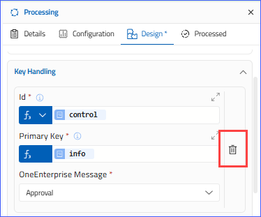
- Upon clicking the Delete icon, a confirmation pop-up will appear.
- Click Yes to delete the key.
- Click No to close the pop-up.
- Once the key is deleted, click on the Save button.
Image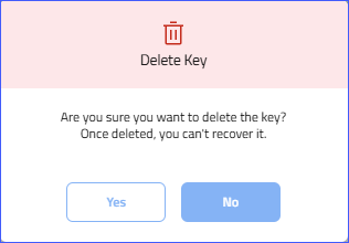
Add Multiple Keys for Key Handling
- You can add multiple keys for key handling.
- Please note that you can add another key after successfully creating the first one. An empty placeholder will always be present. You cannot add an additional key unless you fill in the placeholder values.
- Fill the details in the placeholder, and click the (+) Add icon on the right.
- The new key will be saved, and an empty placeholder will appear at the bottom.
- Repeat the process to add more keys.
Extended Error Handling
Extended Error Handling is an advanced error-management mechanism that enables a flow to detect, capture, process, and respond to errors in a controlled, structured manner. The key functionality of this field is that it does not stop execution; it provides detailed control over how errors are handled.
- Expand the band by clicking it. Once expanded, the following fields will be displayed:
- Condition
- Info
- Category
- All fields are mandatory.
- This Condition field lets you define the condition under which extended error handling applies.
- This field supports only the Fx function and is mandatory.
- The fx icon indicates that this field accepts an expression or formula.
- You can create an expression by dragging a node or nodeset from the outbound messages into the field. Alternatively, you can write the expression manually, use nodes, or combine both approaches to build it.
- To remove a node, press backspace.
- Please note that you can drag and drop any nodeset from the Output section only. Open the output message, then drag the nodeset into the field.
- Create a valid expression.
- The Info field allows you to provide the information for the condition defined in the Condition field.
- The field supports both the Fx and A1 (text field) functions. This field is mandatory.
- By default, the field will open with the Fx function. You can change the field type using the Fx or A1 from the drop-down.
- If Fx is used:
- The fx icon indicates that this field accepts an expression or formula.
- You can create an expression by dragging a node or nodeset from the outbound messages into the field. Alternatively, you can write the expression manually, use nodes, or combine both approaches to build it.
- Please note that you can drag and drop any nodeset from the Output section only. Open the output message, then drag the nodeset into the field.
- To remove a node, press backspace.
- If A1 is used:
- The A1 field lets you enter information manually using the alphanumeric key. A maximum of 10 characters, 0-9, A–Z, and special characters are allowed in the field.
- This is a mandatory field.
- Create a valid expression.
Please note that to fill the expression, you can drag and drop the nodeset from the Output section.
- The Category field is mandatory.
- Click on the drop-down to view the list of available categories. Select an appropriate category from the drop-down.
- Once all the fields are filled, click on the Save button.
Delete Category from Extended Error Handling
- You can delete any category using the delete option.
- To delete any key, click the Delete icon on the right.
- When you click the Delete icon, a confirmation pop-up will appear.
- Click Yes to delete the key.
- Click No to close the pop-up.
- Once the key is deleted, click on the Save button.
Add Multiple Categories for Extended Error Handling
- You can add multiple Categories for Extended Error Handling.
- Please note that you can add another key after successfully creating the first one. An empty placeholder will always be present. You cannot add an additional key unless you fill in the placeholder values.
- Fill the details in the placeholder, and click the (+) Add icon on the right.
- The new key will be saved, and an empty placeholder will appear at the bottom.
- Repeat the process to add more keys.
Output Section
The Output section displays the unit's final output message. The Output Message of the system call unit is the data generated after the unit completes execution. This final output of the unit is then passed to the next unit in the flow. The Output section provides the message in XML and JSON formats.
Message Tab
- By default, the Message tab is displayed, and the message is shown in tree view mode.
Find
- A Find option is also provided to find any node in the message.
- Enter the node name in the search field, and the result will be displayed instantly and highlighted.
- If more than one result is displayed, a navigation icon and a results counter are provided. You can navigate through the search results using the navigation icons.
- To close the search, click the 'x' icon.
Legends
- A legend icon is provided to help you understand the message. The color of the nodes indicates their status.
- Click the Legend icon to view the details. When you click the icon, the list will show the legend used in the message.
Adjust Message Font Size
- A Font Size box is provided to increase or decrease the message's font size.
- The current font size will be shown in the box.
- Click on the box to increase or decrease the font size.
- After clicking the Font Size box, a slider will appear below it.
- Use the slider to increase or decrease the font size.
- As you slide, the change in size will be reflected in the message instantly.
- The supported font size ranges from 8 to 72.
Switch Between Code and Tree View
- By default, the message will be displayed in Tree View.
- Click on the Switch to Code View icon. The message will be displayed in the code view.
- To go back to the tree view, click Switch to Tree View icon.
Related Articles
Edit Component Flow
Overview The flow editor feature in OneEnterprise enables you to visually modify and refine component flow through an intuitive interface. This functionality permits direct interaction with the flow structure of the component. The flow editor offers ...Database Unit
Overview A Database Unit in a flow diagram interacts with a database as part of the workflow. It allows the process to perform structured operations such as reading, writing, updating, or deleting data. What it does: Connects to a database system ...Edit Database Unit
Edit Database UnitEdit Documents Unit (Store Operation)
Overview A Documents Unit in a flow diagram handles document-related operations within a workflow. It’s commonly used to store or retrieve document-style records such as JSON or XML documents. What it does: Manages document objects in the workflow. ...Edit Subscription Trigger Unit
Overview Trigger Units are responsible for starting the execution of a flow. They define how and when a flow is triggered. A flow always begins with a Start Unit, and immediately after that comes a Trigger Unit. The following trigger units are ...